You are here
3D-GD&T Application and Editing
LKSoft’s new IDA-STEP GD&T Editor brings new capabilities to add and edit GD&T and Product and Manufacturing Information (PMI) to 3D STEP models. Now GD&T and PMI can be added and edited to the same data model that is used in analysis, manufacturing, inspection and other processes that traditionally use drawings and CAD model data. This is an essential component of working in a Model-Based Design (MBD) Context. Why put GD&T on a drawing, only to later have to translate and copy it into another system? Why introduce extra steps and chances for error?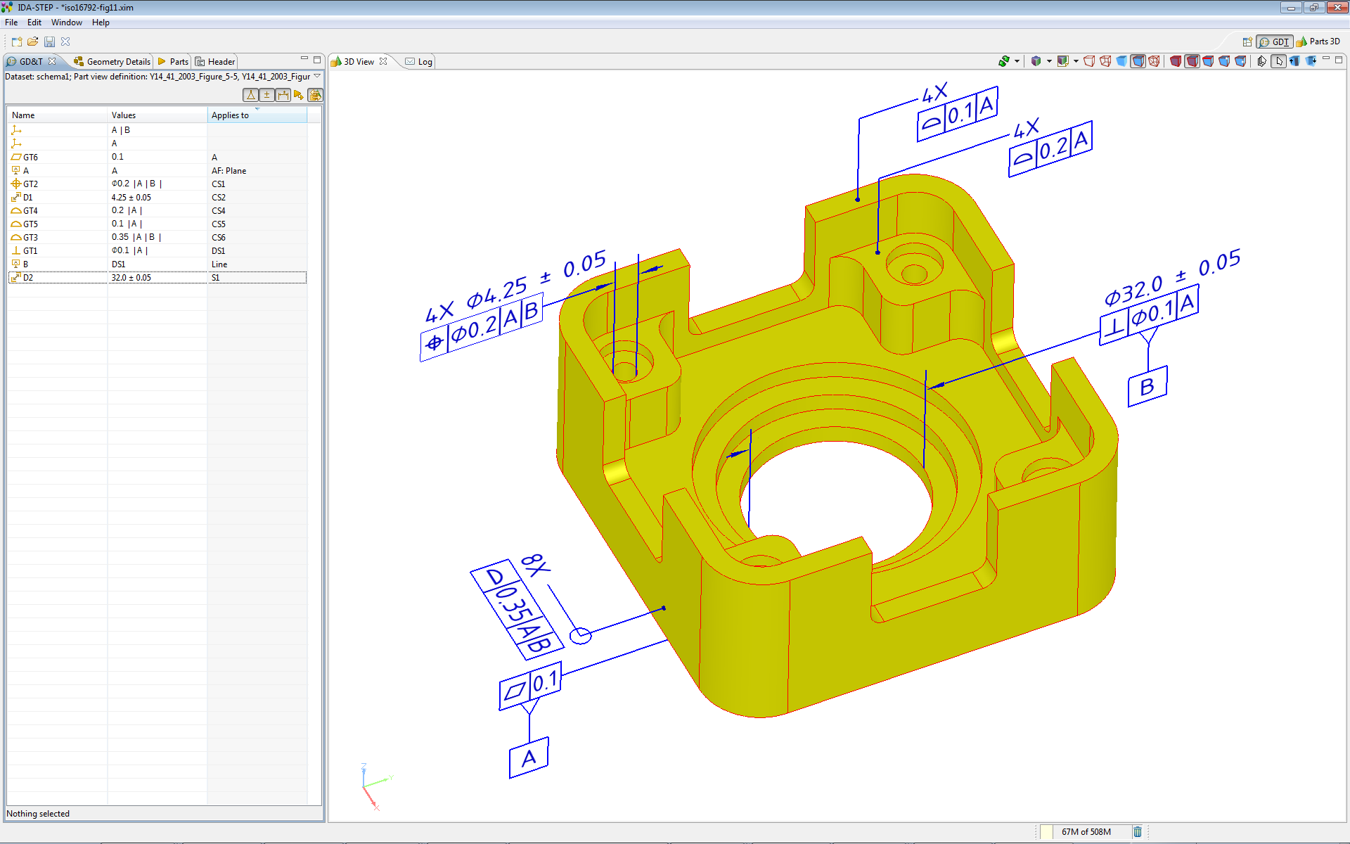
GD&T and annotation have traditionally been applied to 2D drawings. Drawings are created to be used by people, and people must interpret and translate the specifications so they can be used in various processes. 3D CAD systems have advanced the state of the art, and now most or all product design engineering is done in a 3D context. However, today most 3D data is purely model data – it is the geometric data that represents the part or assembly (the product).
2D drawings have been used for many years, but using design engineering data downstream has always been problematic. The engineering drawing had to be translated, by a person, and that translated data reentered into another system for analysis, manufacturing, inspection, etc. This process is fraught with problems and opportunities for error, such as accidentally omitting data or transposing numbers. Any time data is manually-reentered, mistakes may be made. There is also the problem of having redundant data (more than one occurrence of a data element) and management of that data in two or more systems – any changes to the data must be mirrored in each system. This is not an optimal situation.
Working Directly in 3D, Working Directly in STEP
The GD&T Editor works in the IDA-STEP 3D Viewer environment. The user works with neutral, standardized STEP data as a 3D model. The GD&T Editor allows users to visually add or edit GD&T and PMI data directly on the 3D STEP model. This is the same 3D STEP model that is used in downstream processes, such as analysis (FEA, CFD), manufacturing (CAM), and inspection (CAI).
Users will find the tool easy-to-understand, easy-to-use, powerful, and very convenient. Working in 3D with a 3D view of the STEP file is very intuitive. Overall, the GD&T Editor promises not only to be a great tool, but a great way to improve productivity. Perhaps the biggest benefit is that the GD&T and other PMI data is stored in the STEP model as more than just lines and text – not only is the data presented so it is easily understood by a person viewing the model, the data is stored in a computer-readable format.
Presentation and Representation
There are two components to the PMI and GD&T used in engineering product documentation: how the data is presented, including its format, layout, the symbols used, etc.; and what the data means, its underlying mathematical, logical, and legal meaning.
Presentation data is presented for human consumption. It is visible data, presented as notes, dimensions and tolerances, GD&T symbols, surface texture symbols, etc. The data is understood by reading a drawing or an annotated model and correlating it with the applicable specifications and standards. With presentation data, the layout and format of the information is extremely important. Moving a note or a tolerance to a different view, or rotating a dimension 90º generally changes the meaning of the data. Presentation data does not contain its meaning – the meaning of the presentation data must somehow be derived by a human.
Representation data refers to the semantic meaning of the data. It represents the underlying meaning in mathematically accurate terms. The meaning of representation data for GD&T and PMI does not rely on how it is presented on a drawing or an annotated model. Representation data is independent of presentation. Representation data is not for human consumption; it is for consumption by software. Other programs and processes can use the representation data directly without human intervention.
Using the GD&T Editor
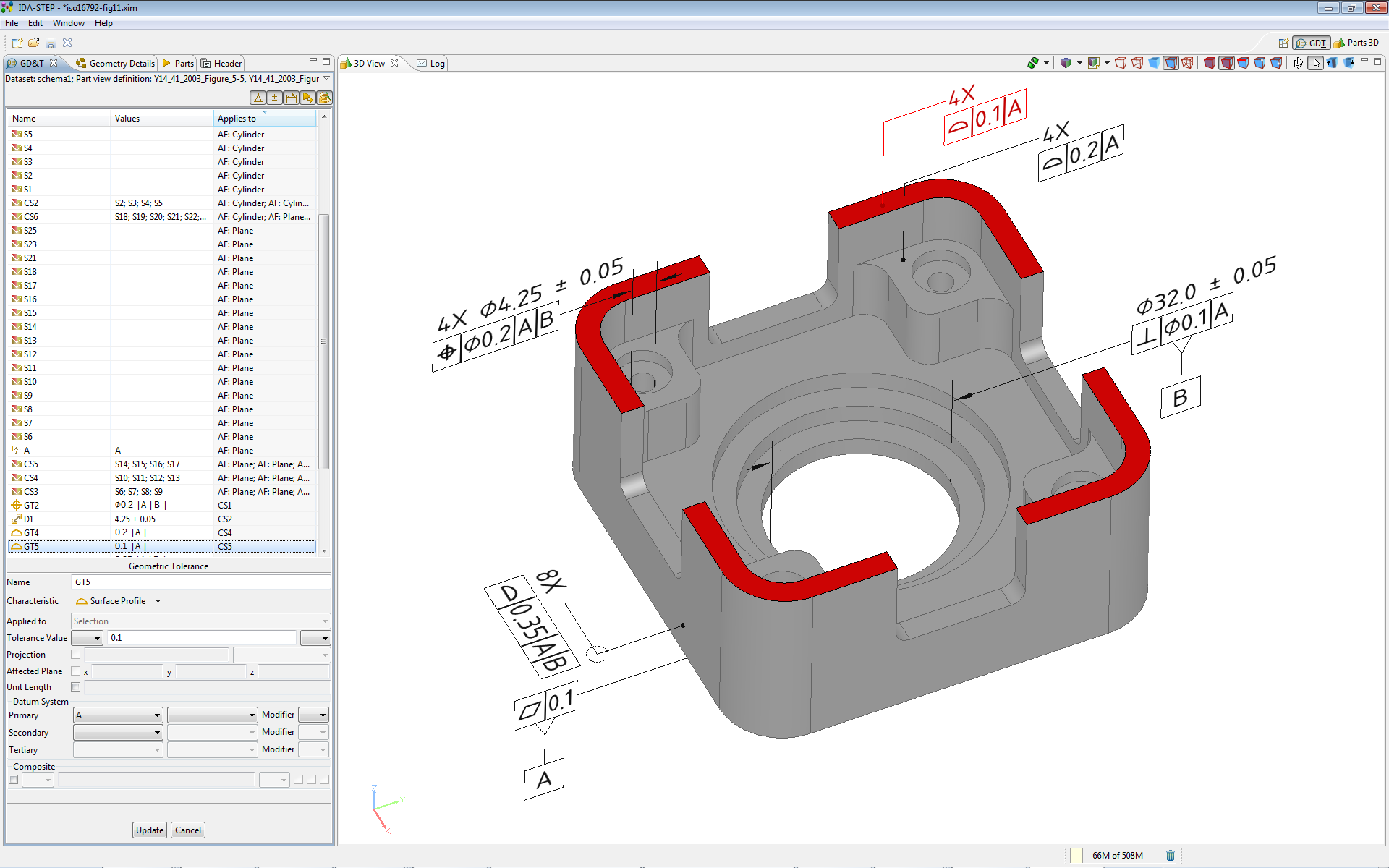
LKSoft’s IDA-STEP GD&T Editor allows users to apply GD&T and other PMI using simple, presentation-oriented methods in a 3D context. The 3D STEP model is displayed in the viewer window, the user applies GD&T and other PMI graphically to the model, and the underlying semantic representation of that data is automatically generated and stored in the STEP model. The process is very similar to putting GD&T on a drawing, but it is done in a 3D context, and the data does not need to be translated into STEP – it is already properly formatted STEP data.
Data may be entered using pull down menus or context-sensitive left-click menus. Users may select the method that they find most comfortable. Do you need to make a change? Making changes to GD&T and PMI with the GD&T Editor is easy. Do you need to add some GD&T or a note to a model? The GD&T Editor makes it easy.
It’s All Based on Standards
One of the defining attributes of the GD&T Editor is that it is based on and conforms to applicable ISO and ASME standards. By extension from the ISO standards, it also conforms to many other international standards, such as DIN, BSI, etc.
First of all, the GD&T Editor works with STEP files. STEP is a neutral file format defined in the ISO 10303 series of standards. IDA-STEP and the GD&T Viewer conform to several STEP variants, including AP203, AP214, and the soon-to-be-released AP242. Users can open and save files in these formats. And there are many programs that can import, read, or use these files directly.
The GD&T Editor supports GD&T and other PMI based on ISO standards and GD&T and PMI based on ASME standards. The user can easily set ISO or ASME as the default format.
GD&T and other PMI are defined in ISO and ASME standards, such as ISO 1101, ISO 14405-1, and ASME Y14.5 respectively. There are many other ISO and ASME standards that define other PMI annotations. The GD&T Editor is built to support these standards. ISO 1101, ISO 14405-1, and ASME Y14.5 define the meaning of the GD&T and Dimensioning and Tolerancing specifications. These standards also set many of the rules for applying and formatting GD&T and PMI, which apply to 2D drawings and annotated 3D models.
There is another layer of standards that govern 3D model structure, presentation of GD&T and other PMI in a 3D model-based context. These are the ISO 16792 and ASME Y14.41 standards. The GD&T Editor supports these standards as well. For example, the GD&T Editor supports creating and editing on multiple annotation planes.
Features of IDA-STEP V4.5 and the GD&T Editor
- Main Enhancements
- New component GD&T Editor (Geometrical Dimensioning and Tolerancing) with basic support of ISO 1101, ISO 16792, ASME Y14.5 and ASME Y14.41
- Allows adding and editing GD&T and other PMI to a 3D STEP model
- Support for MAC OS X, version 10.5 and 10.6
- Many Minor Fixes and Improvements
- Enhancements and New Capabilities:
- New GD&T View window
- Presentation of PMI (GD&T, annotation, callouts) in 3D for human interpretation
- Semantic representation suitable for computer interpretation
- Creation, modification and deletion of dimensions, geometric tolerances, datum features and datum targets
- Selection of ISO or ASME format mode
- Selection of Units (metric or inches)
- Creation and management of annotation planes
- Multiple Annotation Plane support
- Hard copy and PDF output via print engine
- Creation of construction and derived geometry (planes, lines, centre axis, intersection, etc.)
- Easy-to-use
- GD&T data exchange via the upcoming AP242 "Managed Model Based 3D Engineering" and the widely used AP203 (edition 2) or AP214 (edition 3) files
- Geometry Healing: Merging of features (advanced_faces) with the same underlying surface; (e.g. two half cylinders into one)
- Enhanced measurement capabilities beyond what is available in Viewer pro 3D
- Viewer Pro 3D:
- Multiple Selection
- Function "Bring to Front"
Try it Out
So, what are you waiting for? It’s time to try the GD&T Editor. Do you want to annotate 3D models but don’t want to buy expensive CAD software? With the GD&T Editor, you don’t need CAD to work with 3D models and GD&T. You can work with STEP files from any CAD system and annotate them as needed. Remember, the GD&T and PMI is semantically-modeled. That means you can use that data in programs written to consume that data. Without translation. Without additional errors.
Free 30-day Trial!
Take our software out for a free test drive. You will see it is what you’ve been looking for in a GD&T Editor. The GD&T Editor is part of the IDA-STEP viewer, so you will also be able to view STEP data files as 3D models.
It’s time to improve your productivity. It’s time for the IDA-STEP GD&T Viewer!